The Creation of Torsional Pendulum Table Clock 3
Torsional Pendulum Table Clock 3 was conceived from my desire to enhance the lines Torsional Pendulum Table Clocks 1 & 2. I also wanted to improve the mechanism used to adjust the speed of the clock.
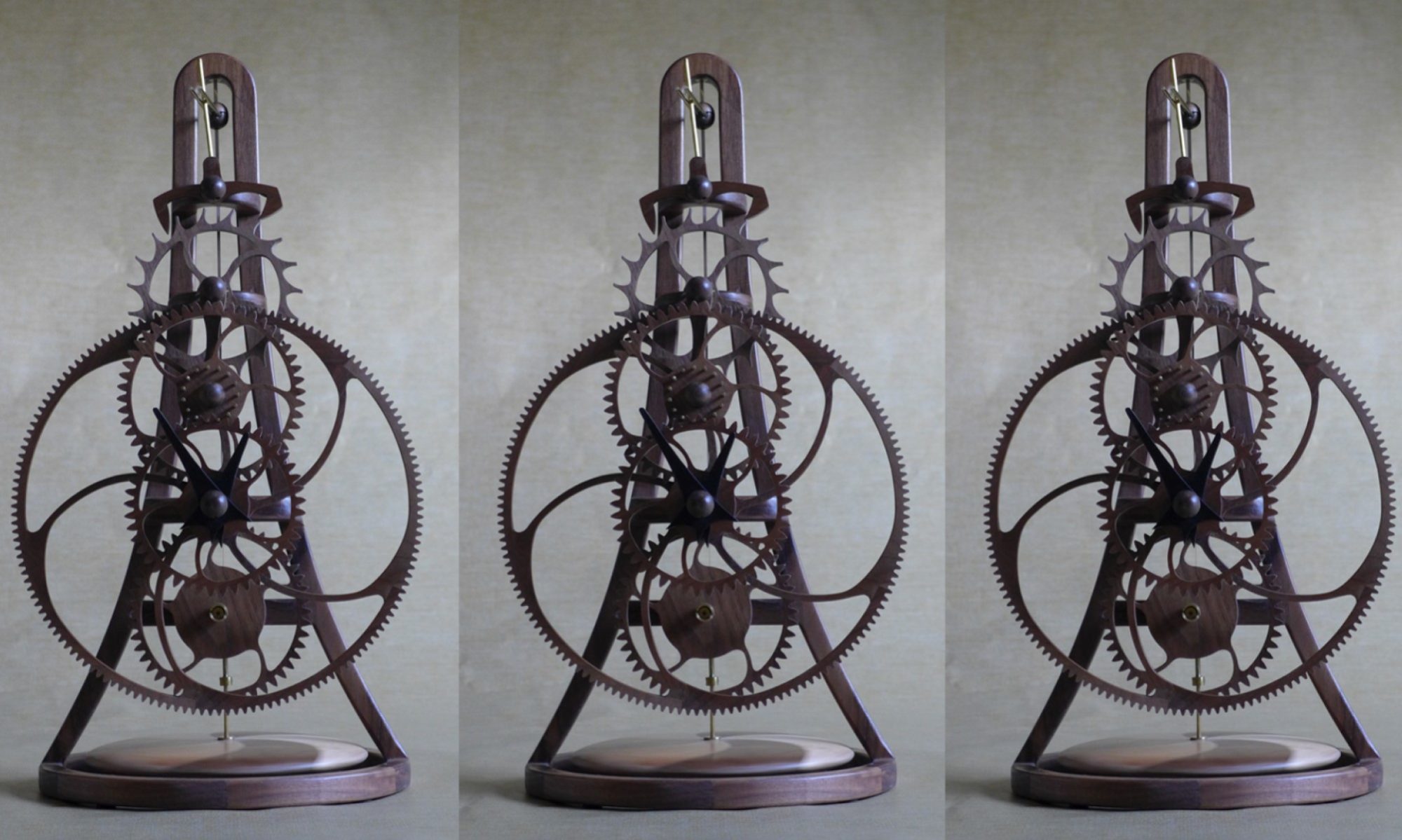
To document the design and construction of this clock, I took photographs throughout the process, which are shown on this page, along with my notes. I hope you find this interesting.
Design
I always start by drawing very rough sketches of different outlines that I work on until I find an overall shape that I am pleased with.

Using the Computer Aided Design (CAD) software TurboCAD, I refine the curves to create a pleasing shape. I achieve this by adjusting the control points of the Bezier splines used to define the curves of the clock outline.


Wood Frame & Wheel Construction
Constructing the clock starts with the acquisition of raw materials: wood, brass, and steel.

Most of the wood is purchased from Ocooch Hardwoods in Wisconsin, USA. The quality of their wood is outstanding, and their walnut is grown locally.
For my early clocks, I cut all the parts on my scroll saws, but I have graduated to using a Zenbot CNC (Computer Numerically Controlled) router. I used the Zenbot CNC router to cut the majority of the components of this clock.

However, I use a scroll saw to cut components that have sharp internal corners that cannot be accurately cut using a router.

The Zenbot CNC router requires the cutter toolpath to be defined in “g-code”. Ventric’s Cut2D & Cut3D software is used to generate the cutter toolpaths.


The most critical part of the clock is the escapement mechanism that sets the clock’s beat (speed). Because of this, it is essential that the escapement wheel and pallet are cut very accurately and do not deform over time. To achieve this, I make my own plywood using 3 sheets of walnut with their grain set in alternating directions. I have tested my earlier clocks for a number of years and had no problems with distortion of the wheels (gears) using this method.


Once all the wood has been cut, the next step is to assemble the clock components.


Assembly of the clock parts is done on a mirror as it is guaranteed to be a flat surface. When needed, the surface of the mirror is covered with waxed parchment paper so that the parts do not adhere to the mirror.


The distances between the “centers” of the wheel (gear) arbors (shafts) are some of the most critical dimensions on the clock. The accuracy of the Zenbot is utilized to drill the arbor holes.

Another critical dimension is the radius of the “teeth” of the escapement wheel. It is critical that the tips of the “teeth” are very close to the same radius. By deliberately cutting the “teeth” to be slightly longer than required allows me to use of the Zenbot to accurately cut them to the correct length on a jig that I designed and built. The jig uses a dial indicator to check the radius of the “teeth”. My goal is to cut the radius of the tip of each “tooth” to within 0.002” of each other.


The enemy of all clockmakers is friction. I learned early on in my adventures in clock-making that it is essential to do everything possible to minimize the friction between components. Although the quality of the surfaces produced by the router is good, I sand each wheel tooth by hand using sandpaper wrapped around a form to give the final shape of the space between the teeth.

Metal Components
Although my clocks are predominantly made from wood, brass and steel components are used where needed. On my early clocks, I relied on metal parts from the local hardware stores and hobby shops that I drilled, cut, and soldered to create the required components. This proved to be very limiting, and I purchased a mini-lathe to give me greater freedom to create clock components, particularly for the spring winding mechanism.
As a “graduate trainee” at Rolls-Royce almost 40 years ago, I learned the basics of metal turning on a lathe, but I have not used a lathe since. I was amazed at how much I remembered about operating a lathe from my Rolls-Royce workshop training.


The clock requires a number of collars to locate the wheels and hands on the arbors. These are easy and fun to make using the lathe, drill press, and thread tap.


Another part that is constructed from brass is the clamp located at the top of the clock frame that holds the torsional spring in place. It is critical that the torsional spring is held rigid. Developing the process to produce a precise slot took me considerable time and many attempts to perfect it.


On my previous torsional pendulum clocks, the clock beat (speed) was adjusted by moving a collar up and down the torsional spring by hand. This has the effect of changing the length of the torsional spring and the period of time between the “tick” and “tock”. Very small movements of the collar were needed to get the clock to accurately keep the time. For this clock, I designed a screw adjustment mechanism to make it far easier to make small changes in the length of the torsional spring to set its speed.

The clock is designed to use “lantern” pinions (the smaller gears) cut from brass rod. A total of 48 pinion rods are needed in this clock. One of the most laborious parts of constructing the clock is cutting these rods to exactly the same length and polishing them.


Frame Assembly
Another critical element of the construction of the clock is to ensure that the base is perpendicular to the vertical frame. To do this, I use a combination of ancient and modern technologies. iPhones contain very accurate sensors and a digital-level app that I use in combination with the ancient technology of a plumb bob and a traditional spirit level to ensure that the frame is square.


Torsional Weight
I do not know why, but I always construct the torsional weight holder last. On this clock, I decided to make it from a combination of walnut and hard maple cut in a “ying-yang” pattern.


Initial Assembly
Before finishing the wood, the clock is assembled to check that it runs smoothly.


Finishing the Clock
All wood components are finished using Watco Semi-Gloss Lacquer.

I have found that keeping the wheel teeth surface as bare wood greatly improves the reliability of my clocks. To achieve this, I cut thin strips of tape to mask off the surfaces of the wheel teeth.

Final Assembly and Tuning
After the wood components have been lacquered, sanded, and re-lacquered, I remove the masking tape and sand all the wheel teeth again with 1500 grit sandpaper to remove any lacquer that has seeped under the masking tape and any residual adhesive from the tape.
The clock is now ready to be assembled and set the beat.


Now comes a few weeks of testing and adjusting to ensure that the clock runs smoothly and keeps good time.
Thanks for your interest in my work.
Richard Cedar.