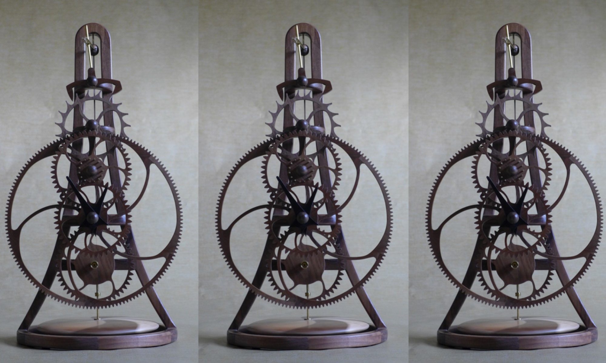
On my smaller clocks I do not cut the great wheel teeth until the wheel is assembled and then cut the center (arbor) hole and the teeth on the rim of the wheel using the CNC router to ensure that they are as accurate as the Zenbot can achieve. Because the diameter of the great wheel for this clock is 21.3” which is larger than the capability of my Zenbot (16” X 24”) so I developed a process where I cut the teeth on each of the 5 segments that make up the rim and then assemble and glue the parts over a full size plot of the wheel. Below are photos of this process.


While the glue dries on the great wheel, I planned to machine the parts that hold the clock frame to the wall from 3/4” diameter brass rod. However, when I measured my brass rod it was 5/8” diameter not 3/4” diameter that I thought. ☹. I have ordered 3/4” diameter rod from Hobby Metals and hope it arrives soon.
As I could not machine the frame hangars, I decided to cut pinion rods from 1/8” diameter brass rod. Cutting and polishing the 67 pinion rods that the clock needs is a rather repetitive and tedious task. The best process that I have found is to cut them to length using the scroll saw using a simple jig to set the length.


The plan for tomorrow is to add the cross members to the clock frame.
I hope you are finding my blog interests. I would be interested in your thoughts, feedback, or questions.

