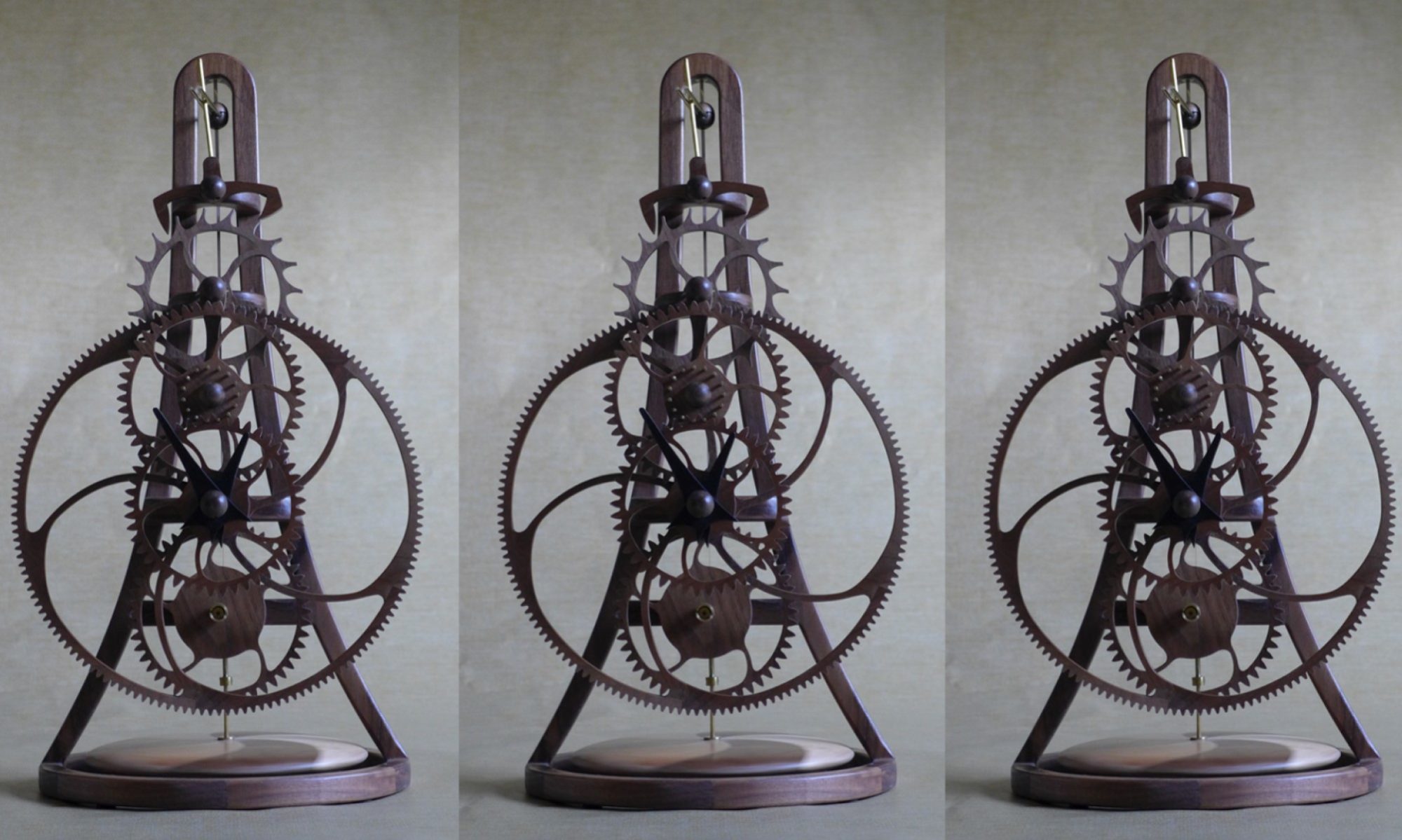
Late yesterday I glued the two halves of the top of the frame together and the components that make remontoire arm and left them to dry overnight.
Below are photos of the remontoire arm once the parts are glued together. The motor, battery, tilt sensor and electronic circuit board will be located in the cutouts.

A challenge on all my clocks is how to hold the top of the torsional pendulum spring. As the speed of the clock is determined by the length of this spring, it is essential to rigidly hold both ends of the spring is essential for good time keeping. I also wanted to be able to remove and replace the spring if necessary. The design I came up with is to create a thin slot in a brass rod that holds the top of the spring. A screw in the side of the rod clamps the spring in place. The photo below shows the upper spring holder on my previous clock.

In this clock the upper spring holder is made from 3/8” diameter brass rod located in the “v-crotch” of the top of the frame. Because accurately drilling a hole to accept the spring holder was going to be a challenge, I designed a jig to hold the top of the frame while I drilled the hole.

Below is a series of photos showing the drill process.


Now that the hole for the torsional spring had been drilled in the top of the frame, I could glue the frame legs components together. I place a mirror on my work bench to ensure that I have a flat surface on which to construct critical part of the clock. (A mirror must be flat so that it does not distort the reflected image.) A full-size plot of the component is taped to the mirror so that the parts can be aligned for gluing and a sheet of parchment paper laid on top to stop excess glue sticking to the plot. I use clamps, tape and weights to hold the part in place while the glue dries.

While waiting for the frame arms to dry, I decided to swap from woodwork to metal work and create the upper spring holder discussed above. The challenge is to create a slot for the spring that measures 0.125” long and 0.007” wide. I start by drilling a 0.125” hole in the center of the 3/8” diameter brass rod using a mini-lathe. I then grind 1/8” brass rod to form two semi-circular pieces that will be soldered in to the 3/8” rod to form the slot. I hold these inserts in place to solder using a thin strip of aluminum from a soda can. Because lead solder does not bond to aluminum, the aluminum strip can be removed after the solder has set to create the slot. The final step is to cut the brass rod to the correct length and clean up the ends on the lathe.


Torsional Spring Holder after Soldering and Cleaning

The plan for tomorrow is to assemble the great wheel.

