After running reliably for a few weeks my latest clock – “Horus” – is keeping good time and is now available for sale ($1600).
Horus – The Smallest Clock from Cedar Clocks
The clock is available with a choice of hand colors. Light natural lacewood hands or black dyed walnut hands. Once can also have a combination of the two colors that like.
Choice of Clock Hand Colors
The clock is powered by a small electric motor in the remontoire re-winding mechanism. The power for the electric motor can be provided by either four AA batteries in a walnut wood battery pack or from a small plug-in transformer.
Battery Box
Plug-in Transformer
Additional information about this clock and my other clocks can be found at the purchase tab of the Cedar Clock website.
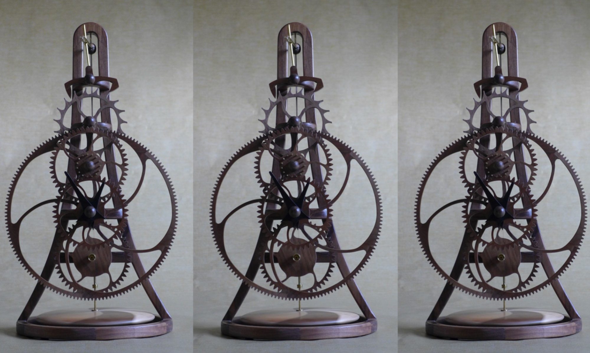
After a long gestation, the smallest clock I have made so far (approximately 16 inches high, 6 inches wide and 5 inches deep) is complete and running well.
I have named the clock “Horus” after the Egyptian god of the sky as its shape is reminiscent of the sign for the eye of Horus.
The clock is powered by an electric powered remontoire (winding mechanism) that rotated around the winding wheel approximately every 15 minutes. Because the clock is so small the 9-volt battery that powers the remontoire motor is located in a separate battery box that is connected by a cable from the back of the clock. I plan offer an option to power the clock from an electric outlet using a small transformer.
I was concerned that achieving the tight tolerances required to construct a clock this small would be a challenge. This did not prove to be a problem, but I struggled finding the right combination to torsional pendulum spring and weight as well as the correct dimensions for the pallet fork to get the clock to run well. After considerable experimentation with different spring thicknesses and pendulum weights, I found a combination that works well.
On my previous clocks I have not had any issues with the wooden wheels (gears) warping. I originally use three layers of 1/16” thick walnut, with the grain in alternating orientations, for the main wheel of the clock. Initially, this looked great and the clock ran well, but over a few weeks the wheel gradually warped until they looked like potato chips and the clocks stopped running. To solve this, I created wood laminates from 1/40” thick walnut veneer. I remade the main wheel uses 7 veneer plies and the other wheels 5 veneer plies, alternating the grain direction. The clock had been running for a few weeks with the new wheels and there is no sign of warping.
I plan to run the clock for a few more weeks before I offer it for sale.
As the Mini Clock escapement and wheel train test rig has been running well, I have been designing the complete clock. The overall design is similar to my last clock “Electra 2” (https://cedarclocks.com/photos/) but much smaller and rather than wall mounts, it has a base so that it can sit on a table.
Current Design of the Mini Clock
The clock is approximately 14.6” high, 6.0” wide and 5.1” deep. I am fairly happy with the overall design but being a small clock, it does not require much wood so, if I decide I do not like the design, I could redesign and re-make parts without a huge cost.
The next step is to start cutting out the components primarily from walnut wood but I plan to use lignum vitae for the pallet. Lignum vitae is a very dense wood that has self-lubricating properties that is ideal for the escapement pallet. I will start by cutting the components of the escapement and wheel train.
Following a couple of months hiatus from clock making, while I made a sundial and small table for my house, I am thinking about the design of my next clock. My idea is to challenge myself to see how small a clock I can make with my current equipment.
The diameter of the main wheel in my last clock has a diameter of approximately 21 inches. My initial calculations show that, with my current equipment, I could make a similar clock at about a quarter the size, so that the main wheel will have a diameter of just over 5 inches.
The first challenge is going to be to find the right size spring for the torsional pendulum. I am exploring using a torsional pendulum suspension spring from a Holovar 400 Day Clock (also known as an Anniversary Clock). I purchased several different size suspension springs and built a crude escapement and main wheel test rig with plywood wheels to determine the combination of spring and torsional pendulum size / weight that will give the required beat (the time between clock ticks) of about 5.3 seconds.
Mini Clock Escapement & Wheel Train Test Rig – The Main Wheel is 5.7 inches Diameter with 125 teeth
My initial test indicates that a Holovar spring with a length of 7 3/8” and 0.004” thickness will give me the desired beat.
I am really happy with the electric powered remontoire (winding mechanism) that I have used on my last two clocks and would like to use a similar winding system on this clock. I have found a source of tiny geared electric motors that could be suitable for this clock. I have one on order to see if it will be suitable.
Unlike my last clock that was designed to be mounted on the wall this clock will be a table or mantel clock with a height of about 12 inches although I still need to complete the detail design.
The clock was still running this morning and I spent today replacing the brass bearing tube that was too short, trimmed the arbors and the pallet fork to their final lengths and permanently glued components that were press fit together.
I made the video below as I re-assembled the clock.
Video of the Assembly of the Clock
The clock is running well and the only things left to do are to make the final adjustment to the torsional spring length so that the clock keeps good time and run the clock for a few weeks to make sure that it is reliably.
Once I am happy that the clock is keeping good time and running well, I will offer the clock for sale. To be consistent with the “pandemic pricing” of my other clocks (see the Purchase page), I am asking $2500 for this clock. Please contact me at richard@cedarclocks.com if you are interested in purchasing the clock.
It has been almost exactly a month since I started daily posts on the construction of the clock. Building the clock and writing these blogs has kept me busy in these strange times. I hope you have found them interesting. This is my last daily blog but I will write additional posts if there are any interesting updates and I plan to share detailed photos and a video next week.
Started today by permanently gluing the 67 pinion rods in place and mounting the wheels on the arbors. Initially, the clock ran intermittently. Inspection revealed that more lacquer than expected had seeped under the masking tape on some of the great wheel teeth, so I lightly sanded them, re-assembled the clock again and it ran much better.
Finished & Re-Assembled Clock Running 😊
I did not get to the hardware store to buy the bass tube that I need until late today, so I used the tube I had and will replace it tomorrow.
As I write this, the clock has been running well for over 4 hours and I am hopeful it will still be running tomorrow morning.
The plan for tomorrow is to replace the brass tube bearing that is too short, permanently glue the arbors to the frame and trim the pallet forks to their final lengths. After that, the only things left to do is check that the clock runs consistently and adjust the length of the torsional spring until it keeps good time.
A cold rainy southern Ohio day so I spent time applying a number of very light coats of lacquer to the clock hands until I was happy with the finish – They look good – and sanded and re-lacquered a few other parts that I was not totally happy with. Enough lacquering, the clock is ready to re-assemble.
Started by assembling the remontoire winding arm that includes the winding motor, electric circuit board and the battery. See earlier post for details.
Assembled Remontoire Arm and Winding Wheel showing Battery Compartment
Remontoire Arm with Battery Compartment Closed
The back of the Remontoire Arm is fastened with wood screws so it can be opened should one need access to the electric motor or circuit board
Also attached the arbors (shafts) and mounting hardware to the clock frame so I am ready to assemble the wheel trains. However, I need to purchase some brass tube as one of the bearing tubes is about 1/8” too short. This was not an issue while I was testing the clock but not for the final product. I will have to visit the hardware store tomorrow.
Finishing the clock is the slow part of clock construction. I reviewed the surface finish quality on all the parts, sanded areas that I was not happy with, applied another coat of lacquer where needed and left them to dry. There was nothing else to do other than wait for the parts to dry which was OK as it was warm and sunny and it was a pleasure to be outside.
By the end of the day all the parts were looking good other than the clock hands which need more work to get the surface quality I want.
Rain forecast again tomorrow, but there is little more I can do other than sand and re-lacquer the clock hands and any other areas that I decide need some more work.
The weather forecast was correct – Today was gray and rainy in southern Ohio, ideal to lightly sand the lacquered wood parts and the application of a second coat of lacquer.
Parts Laying on Newspaper to Dry after Lacquering – A very basic set-up
Wheels Hanging to Dry on Wire Rods through the Arbor Holes
Lacquer brings out the beauty of the wood grain but it also highlights any imperfection in the surface finish. To stop the parts moving as they are being cut out by the CNC router, I add tabs to hold the part to the surrounding wood. These tabs are then cut and the sanded smooth. However smooth I think that I have sanded these tabs, the application of lacquer highlights where they were and I have to re-sand the surface. Excess glue from joints that was not cleaned off also shows up after lacquering, especially on end grain wood.
Although the second coat of lacquer is still drying, I am pleased with the surface quality on most of the parts. A few parts will need a third coat and, even though I try hard to apply a thin coat of lacquer, a few runs have appeared that I will let dry, sand smooth, and re-lacquer the local area.
The plan for tomorrow is to re-sand the parts that need it and apply another coat of lacquer.
After weeks of gray skies and rain in Cincinnati, Ohio, we have beautiful spring weather today, so working outside in the yard was far more attractive than sanding clock parts in the workshop. I declared today a rest day from the clock. The weather forecast for tomorrow is rain so I plan to resume working on the clock.
It is difficult to write anything very interesting about lacquering the clock parts. I use Watco Semi-Gloss aerosol lacquer that I spray on most of the parts laid out on paper. The wheels are held on a “shaft” so that I can rotate / spin them one at a time as I spray them trying to get an even covering on the rims, spokes and hubs. The spraying process is very inefficient, most of the lacquer misses the part, so I will go through several spray cans before I am happy with the finish. However, I have found that I get a better finish by spraying multiple thin layers than trying to apply lacquer using a brush.
Watco Semi-Gloss Lacquer used to finish the clock parts
Wheels on a metal shaft so that I can spin them as I spray lacquer
Today, I sprayed one side of each part, waited for them to dry, turned them over and sprayed the other side. I will leave the parts to dry over night and tomorrow I will sand as many of the surfaces as I can with 400 grit sandpaper, clean them with tack clock and then apply a second coat of lacquer. My experience is that this will result in a good finish on some of the parts, but depending on the wood grain size and orientation, some parts will require a third, fourth, or even a fifth coat. About as interesting as watching lacquer dry. 😊
Sanded the final parts and then it was time to clean up the workshop that took most of the day.
Wooden clock parts sanded and ready for lacquering
My experience, and that of other wooden clock makers, is that wooden clocks run much better if the wheel teeth are kept as bare wood, not varnished or lacquered. As I plan to finish all the wood parts using aerosol sprayed lacquer, I mask off all the teeth surfaces with long strips of masking tape prior to spraying.
Masking wheel teeth with long strips of masking tape
Masked wheel reading for lacquering
Tomorrow it’s time to apply the first coat of lacquer.
As the clock is running well, and keeping good time, it was difficult to take it apart to start the finishing process. Everything that was not permanently glued together has been disassembled and the wooden parts laid out for sanding. I started with the frame that still needed considerable work blending the cross pieces in to the uprights. I followed with the wheels and other parts using a sanding block where possible and folded pieces of sandpaper for the curved surfaces. All surfaces are finally sanded using 400 grit paper.
I like to slightly round all edges (“breaking the edges”) by running a piece of sandpaper along them so that they are no longer sharp. I learned from my days as a potter that even slightly rounding edges gives the piece a dramatically softer appearance.
My plan is to have everything sanded before I start to apply lacquer to minimize the amount of dust in the air that can land on the surface while the lacquer is drying.
As mentioned in an earlier post, the clock hands will be dyed black so that they stand out from the rest of the clock. Because it takes time for the dye to dry, and it normally takes three or four dye applications followed by sanding, I dyed the hands today using TransTint black dye diluted with water.
Hands hanging to dry following dying
The plan was to sand all the part today but it did not happen and I have a few parts left to sand tomorrow. I try to clean the worst of the mess from my workshop at the end of each day, however sanding leaves every surface covered in dust that I will clean up when I finish sanding tomorrow. A necessary but not fun task.
Accomplished another milestone today with the manufacturing of the final parts of the clock, the hemi-spherical walnut caps that cover the brass collars on the end of the arbors and the collar on the torsional pendulum fork. These caps serve no functional purpose, purely decorative, but I think they give the clock a “tidier” appearance. The hemi-spherical caps are formed from walnut dowel rod, using a conventional router to round the end. For the ¾” diameter caps, I use a 3/8” radius cutter with the router set-up so that as the dowel is rotated the cutter forms the hemi-spherical end to the dowel.
Using router to cut the hemi-spherical end on the walnut dowel
The end of the dowel rod is then cut off and I use the lather to drill the cavity in the dowel for the collar and cut off the hemi-spherical end cap.
Drilling the cavity in the cap using a drill collar to set the depth
Cutting off the hemi-spherical end cap
Finally, a hole is drilled in the side of the cap to access the collar clamping screw.
Drilling access hole for the collar clamping screw
Some of the walnut caps manufactured today
Clock with the walnut caps installed
Next step is to disassemble the clock and sand all the parts in preparation for finishing the clock with lacquer.
The properties that make walnut ideal for wooden clocks, fine grained and hard, make it hard work and time consuming to sand, but once it is smooth the surface finish is beautiful Today, I sanded the other half of the torsional pendulum, mated the two halves, sanded the joint and installed it on the clock.
Upper and Lower Halves of the Torsional Pendulum
Complete Pendulum
Video of the Clock Running with the Torsional Pendulum
Although constructing the torsional pendulum is very time consuming, in my opinion, it really changes and improves the dynamic impact of the clock.
There are only a few components still to made, the hemispherical end caps that I use to cover all the brass collars. I plan to construct these small fiddly parts tomorrow.
Sanding, checking the assembly, gluing and more sanding was the order of the day as I worked on the torsional pendulum. I started by sanding by hand but soon realized that I needed a better solution so I designed and constructed a fixture to hold half the torsional pendulum in the lathe and use the lathe to sand it.
Fixture holding half the torsional pendulum for sanding
I started with 60 grit and proceeded through 120, 220 and 400 grit to smooth the surface of the first half.
Torsional pendulum after sanding with 400 grit sandpaper
External surface of the torsional pendulum
Internal surface of the torsional pendulum
There are still a few surface imperfections that I will sand out. I plan to do this tomorrow after I have sanded the other half of the torsional pendulum and can mate both halves of the pendulum and sanded the joint.
Past a major milestone today – The clock has run continuously for over 24 hours and is still running with a strong “tick”. My experience is that once a clock runs for a day all the “problem teeth” have been corrected and it will continue to run indefinitely.
Video of the clock running with the temporary torsional pendulum
Today, I cut the other side (the walnut side) of the torsional pendulum on the CNC router. Next step is to glue the parts together and sand the surface smooth.
Torsional Pendulum Parts ready to assemble
As the surface finish is not as good as I would like, I am thinking about making a fixture to hold the torsional pendulum halves in my lathe to speed up sanding.
Tomorrow, I plan to start assemble the torsional pendulum and perhaps make the final parts needed for the clock, the arbor end caps.
The domestic tasks did not take too long and I managed to cut one side (the maple side) of the torsional pendulum on the CNC router. I’m concerned that my ¼” ball end cutter is not as sharp as it should be as the surface finish was not very good, but nothing a few hours of sanding will not correct.
Zenbot CNC router cutting the maple side of the torsional pendulum
The clock continues to run well.
As there is not much news today, I thought you might be interested in more technical details on the clock. Below is a summary of the teeth on each wheel and pinion. This tooth count result in a beat (the time between ticks) of 6.3 seconds or 570 beats per hour.
Number of teeth on each wheel and pinion
The plan for tomorrow is to cut the other side (the walnut side) of the torsional pendulum.
Recall that yesterday I found an issue with the clock design that resulted in the clock running too fast. To remedy this, I need to increase the moment of inertia of the torsional pendulum but there is not enough room in the current pendulum design to increase the number of weights. My original thinking was to increase the diameter of the pendulum allowing the weights to be moved radially outward. I gave this some more thought this morning and realized increasing the pendulum diameter would have several undesirable consequences. While pondering what to do, it occurred to me that if I re-orientate the weights the radius of their center of gravity would move outward increasing the pendulum’s moment of inertia. I tested this on the temporary pendulum and it worked beautifully, the clock is keeping good time and I could reduce the number of weights so that they fit in to the original pendulum.
Original Torsional Pendulum Weight Configuration
New Torsional Pendulum Weight Configuration
The rotation of the torsional pendulum is the primary kinetic element of the clock and on most of my clocks I use two contrasting woods to accentuate the visual impact of this motions. The design for this clock is a 4.5” diameter spherical torsional make from walnut and hard maple.
Digital representation of the Torsional Pendulum showing the contrasting woods design
The pendulum is partially hollow with cut-outs to accommodate the weights. My plan is to cut the pendulum on the Zenbot CNC router. Because of the router cut depth limit, the pendulum will be constructed from 6 layers of ¾” thick wood. Each layer will be cut and then glued together. To get access to the weights, the pendulum is split horizontally with dowels to locate the upper and lower halves. Each layer is defined in my CAD software, TurboCAD, and the CUT3D software from Ventric is used to create the g-code toolpath. Because I rarely use this software it is always a learning experience and I spent most of today struggling to work out why it was not doing what I expected. I eventually worked it out and have generated the cutter path g-code files.
CUT3D simulation of the machining of the 6 layers needed to construct half the torsional pendulum
While working on the torsional pendulum I was testing the clock and tweaking the teeth when it stopped. The clock is now running well and I am keeping my fingers crossed that I have corrected all the “problem teeth”. However, experience on previous clocks is that lacquering the wheels will result in them distorting very slightly requiring additional tweaking.
I have several domestic tasks to do tomorrow, so I am not sure if I will get to cutting the torsional pendulum.
The clock ran for over 5 hours last night. Rather than chasing the last few “problem teeth”, I decided to concentrate on making the clock hands and the clock speed adjustment mechanism today.
The clock speed is regulated by the moment of inertia of the torsional pendulum and the torsional stiffness of the torsional pendulum spring. The inertia of the torsional pendulum is controlled by the number of weights in the pendulum and the distance of these of the weights from center of the pendulum. The torsion stiffness of the spring is set by the width, thickness and length of the spring. During the design and construction of the clocks the number of torsional pendulum weights and their radial location is set so that the clock keeps good time. I have developed a screw adjustment mechanism that changes the effective length of the torsional pendulum so that the clock owner can fine tune the clock speed. Below are a series of photos on the construction of the clock speed adjustment mechanism.
Creating a slot in the top of the Spring Length Adjustment Tube
Slot in the top of the Spring Length Adjustment Tube after Soldering and Clean-up
Components of the Clock Speed Adjustment Mechanism
Completed Clock Speed Adjustment Mechanism
I leave the construction of the clock hands until I have nearly completed the clock so I can decide what shape to make the hand to compliment the clock design. My plan was to use a different wood for the hands so that they stand out from the clock, but with my local wood suppliers closed I will make the hands from walnut and dye them black. One cannot cut sharp internal corners using a router so I print the hand design on paper which I glue to the wood and then cut out with a scroll saw.
Hand Design Glued to ¼” walnut sheet
Cutting the sharp internal corner of the hand on a scroll saw
Scroll saw cut hand
Because the pointer (finger) end of the hand is heavier that the other end, the hand is balanced by adding a brass disc to the other end (there must be a correct term for this) of the hand.
Using fishing weights to determine the weight required to balance the hand
Brass discs are cut on the lathe to give the weight required to balance the hands
Current Status of the Clock – Note that the hands will be dyed black so that they will stand out
When I assembled the clock with the speed adjustment mechanism, I had a nasty discovery. As the torsional pendulum rotated it hit the clock frame ☹. To remedy this, I shortened the torsional spring by about an inch which caused the clock to run fast. To get the clock to keep time, I had to add more weights to the torsional pendulum. Unfortunately, the number of weights that are now required will not fit in the current design of the torsional pendulum and I will need to re-design it. My current thinking is to increase the diameter of the torsional pendulum by about ½” inch so that the number of weights can be reduced as they can be moved to a greater distance from the center of the pendulum. Tomorrow’s task is to think through the options and re-design the torsional pendulum.
This morning I made some temporary clock hands so that I can tell how long the clock runs before stopping and whether the clock is running fast or slow. I then followed my standard practice for debugging the clock. Run the clock until it stops, looks at the teeth engaged when it stops, sand any imperfections and mark the teeth with a piece of tape, re-start the clock and repeat the process.
Marking Problem Teeth with Tape
If the clock continues to run past the teeth that I have marked I remove the tape marker. Hopefully, over a few hours the number of teeth marked keeps reducing until none are marked and the clock keeps running. Unfortunately, by lunchtime the clock kept stopping, there were no obvious issues with the teeth, and I realized that there was another problem.
I started tweaking some of the other parameters that I knew could be the cause of poor running. I changed the weight on the remontoire arm, no joy. Then, I changed the fore/aft location of the intersection of the pallet stem and the torsional spring form. As I reduced the effective length of torsional spring fork the clock began running better. I judge this by the “strength” of the tick-tock sound.
Pallet stem position at the start of the day – Clock not running well
Pallet stem position at the start of the day
Pallet stem position at the end of the day – Clock running well
I kept adjusting this length until I had a strong “tick-tock” and the clock was running well. I then went back to the process I use correct problem teeth. By mid-afternoon I had removed all the tape marking problem teeth and at the time of this post the clock has run for 4 hours and is still going.
During this process, I have been changing the weights on the torsional pendulum to adjust the clock speed. The clock is now keeping great time for this stage in its development.
Clock with the Temporary Hands
Weights on the Temporary Torsional Pendulum Adjusted until the Clock was keeping good time
If the clock continues to run, I have two tasks for tomorrow – Cut the actual clock hands and construct the clock speed adjustment mechanism.
With the clock running intermittently, the task becomes finding the teeth with small imperfections and sanding them smooth. I started by sanding each tooth on the great wheel with 400 grid sand paper to smooth off the cutting tool marks.
Sanding a great wheel tooth
I then assembled each pair of meshing wheels in turn and rotated them by hand to see if I could feel any problem teeth. I found several teeth that needed minor sanding. I then assembled the going train of the clock and started it running. When it stops I inspect the meshing teeth and sand any that looked suspect. My experience is that I will need to continue this process for a few days, each day the clock will run longer before stopping, but once the last imperfection if smoothed the clock will run continuously with no problems.
Tomorrow – More tooth sanding, testing, tooth sanding, testing…
Started today by assembling the clock without the pallet so that it would run freely and rotated the great wheel by hand. Everything ran freely. I added a temporary weight to the remontoire arm but did not connect the battery and set the arm at the top of its arc and let go. The clock turned under the power of the weight. See video below or at my website (https://cedarclocks.com/the-clock-runs-for-the-first-time) if the video does not transfer to Facebook.
Video of the first rotation of the clock wheels under the power of a temporary weight on the remontoire arm
I then connected the battery so that the winder motor would run when the remontoire arm reached the bottom of its arc.
Video of the clock wheel rotating with the winder motor connected
The only parts remaining to be constructed before I could test the clock, including the torsional pendulum and escapement, were the pallet stem and the torsional pendulum weight. The pallet stem links the pallet to the torsional spring fork. The fore / aft location of the pallet stem (the location of the intersection with the torsional spring fork) is a critical dimension as it sets the rotational amplitude of the pallet, effectively the point in the cycle that the pallet gives an impulse to the torsional pendulum. I have found, through trail and error, that if this dimension is not correct the clock will run very poorly or not run at all. I set this dimension based on my experience on previous clocks.
Pallet Stem is with excess material to allow the fore/aft location to be adjusted
I always make a temporary torsional pendulum weight holder so that I can easily change the weights to determine how much weight is required to get the clock to keep time. Nothing left but to see if the clock runs. After a couple of minor adjustments, it ran… not particularly well… but it ran for a few minutes.
Video of the first ticks of the clock 😊
I had decided not to sand the great wheel teeth as the surface finish looks reasonable and I was impatient to see if the clock run. The clock appears to be stopping on teeth that that I can see are rough.
Tomorrow’s tasks: Sand the teeth of great wheel to see if I can get the clock running smoothly, make some temporary hands and adjust the torsional pendulum weights so that it keeps time.
I was in a hurry to publish yesterday’s post and did not include photos of how I ensure the clock is hung vertically and the lower clock supports so I will start today’s post with them.
I use a simple plumb bob hung from the Torsional Spring Support to determine if the clock is vertical
Plumb Bob hanging from the Torsional Spring Support at the top of the Frame
The two lower brass frame supports have pins on the end that I use to make marks on the wall that I will use to drill holes to insert them
To make progress I had no choice but to cut the remaining 20 pinion rods and polish all 67 of them. This is my least favorite tasks.
Polishing the pinion rods in the drill press using a file and 1500 grit wet and dry paper
On previous clocks the pinion rods were a push fit in their holes. On this clock the brass rod diameter is very slightly smaller than the nominal 0.125” and I suspect the holes are minutely large so that the pinion rods are a sliding fit. Ultimately, this will not be a problem as I will glue them in place, but I want to run the clock to check it runs well before I remove the pinion rods to finish the clock. I decided to dip one end of each rod in the Watco lacquer that I will use to finish the clock before inserting them in to place. This should be good enough to hold the pinion rod for initial testing.
Newly polished pinion rod held in place by Watco lacquer for initial testing
With any luck, tomorrow I will assemble the clock and see if all the wheels turn freely. If they do, I will make the final few parts required to “set the clock to beat” and see if it will run.
After a day of lathe work, the clock (as is) is hanging on the wall.
At the end of today the clock (as is) is hanging on the wall
It is amazing how much better the lathe is running after yesterday’s adjustments and I turned all the brass parts that attach the clock frame to the wall with no problems.
When I designed these parts I was very conscience of an experience from about 40 years ago when I built some shelves for my first house (built in ~1815) in Derby, England. The shelves were to be located in the corner of my bedroom and I worked hard to ensure that they were square, all the corners were right angles. I was very happy with the results until I tried to hang it on the wall only to find that there was a large ugly gap between the shelves and the wall. The shelves were square but the corner of the room was not quite a right angle and I had not thought to check before I started. On this clock the torsional pendulum spring runs very close to the clock frame and the clock will not run if the spring touches the frame. If the wall the clock is hung on is vertically this will not be a problem. Remembering my house in Derby, there is no guarantee that the wall will be vertical and I need to include provision to adjust the clock hanger to accommodate an imperfect wall.
Below are a series of photos showing the attachment of the clock to the wall.
Hanger Bolt Screwed into the Wall
Threaded Brass Rod Screwed on to the Hanger Bolt
Grooved Collar Threaded on to Brass Rod.
To compensated for a non-vertical wall, the distance of the top of the clock from the wall can be adjusted by changing how far the collar is threaded on to the brass rod.
Brass insert at top of the clock frame. A threaded hole in the side of the insert accommodates the locking set screw that seats in to the groove on the collar.
Tightening the Locking Set Screw into the grooved collar to secure the clock on the wall
Two Brass Rods with pins on the end attach the bottom of the clock to the wall
I can’t put off cutting and polishing the remaining pinion rods much longer, so that is my plan for tomorrow… but I could cut the clock hands.
The day started well when I started pulling out the electronic components required to control the electric motor that winds the clock “remontoire” and found that I had an assembled set of components that I had built as a spare for my last clock. I decided to use this and wire it to the new motor that I bought for this clock.
I discussed the remontoire and choice of electric motor in an earlier post (https://cedarclocks.com/the-new-clock/ ) that included a video of my last clock in which you can see the remontoire operate at about the 60 second point in the video. The remontoire motor is controlled by a tilt sensor, when the angle of the remontoire arm rotated below a given angle a small steel ball in the tilt sensor rolls down the sensor tube on to a set of contacts reducing the resistance across the sensor to almost zero. When this happens the circuit is designed to activate the motor that winds the remontoire wheel up the winding wheel until the angle of the arm causes the steel ball to roll back down the sensor tube resulting in an open circuit that stops the motor.
In theory, one could wire the tilt sensor between the motor and battery and the system should work. However, the motor draws a larger current that the tilt sensor is designed to withstand for long term use so I decided to use a MOSFET switch. The MOSFET switch is activated by the tilt sensor, however, only a very small current passes through the sensor and the larger current required by the motor passed through the switch.
I developed this circuit on my last clock, Electra, and, as I only have a basic background in electronics, I was very happy when it worked first time. However, after a small number of operations it stopped working and it became clear that the MOSFET switch had failed. I tried again with a second switch with the same result, it worked a few timed and then the MOSFET failed. I assumed I had a bad batch of switches and bought a few new switches from a different source. The first of these switches failed in the same way as the previous ones. I consulted Google and soon found that this a well know issue when using a MOSFET switch to control an inductive load like a motor and I needed to add a “flyback” diode to the circuit. The reason for this is explained in the Wikipedia article https://en.wikipedia.org/wiki/Flyback_diode. Once I added a flyback diode the circuit worked well. How did we do stuff like this before Google?
Below are a series of photos of the electronic set up and the remontoire arm. The tilt sensor is the gold colored component on the right of the circuit board. Finally, I took a video of the remontoire motor operating when I tilt it by hand.
Electronic Circuit Board with Tilt Sensor on the Right
Remontoire Arm (backplate removed) with, from left to right, the electric motor, battery, circuit board and tilt sensor
Video of remontoire motor operating when the arm is tilted by hand
Having successfully assembled the remontoire arm I decided to start working on the brass parts that attach the clock to the wall. The first part requires cutting 24 turns per inch thread on the end of a 3/8” diameter brass rod. I decided to cut this thread on the lathe rather than use a die. I have very little experience thread cutting on my lathe so I knew it was going to be a learning experience. My first attempt failed when the cutting tool jumped and ruined the thread. I tried again making very small cuts but it became clear that there was an issue with the lathe as the cutting tool kept jumping leaving a very poor cut. I investigated and found that the lathe saddle was loose on the lathe bed. These Chinese made mini-lathes are excellent value for money, but to adjust anything requires completely disassembling the lathe. Two hours later I had striped down the lathe, adjusted the saddle slide, cleaned everything and re-assembled it. I cut a couple of simple part and the lathe was cutting very smoothly leaving a much better surface finish that I have achieved recently so I suspect that the saddle has been coming loose for some time. Tomorrow, I will re-try cutting the thread.
The 3/4” diameter brass rod that I need for another part of the clock hanger arrived today so I plan to cut that tomorrow with my newly adjusted lathe.
A light day of clock making today as it was my turn to shop for the week’s food. I never thought that I would be selecting vegetable at the supermarket looking like a bank robber in my homemade mask.
After returning and putting everything away I was not in the mood for sanding the 312 wooden gear teeth that make up the clock. I went down the “to-do” list and decided to tackle the most complicated metal component in the clock – the “torsion pendulum spring fork” that transmit the motion of the torsional pendulum spring to the escapement pallet.
Below is a photo of the “torsion pendulum spring fork” on my previous Electra clock.
Torsion pendulum spring fork” on my previous clock – Electra
Note that you can only see the brass forks as the remainder, the body, is hidden under the spherical wooden cover.
The “torsion pendulum spring fork” clamps to the torsional spring using a set screw so that its position on the spring can be adjusted.
On a previous clock I make a small steel jig to hold the body of the part and allow accurate drilling of the three holes, one for the clamping set screw, and two for the forks that are made from 1/8” diameter brass tube.
Torsion pendulum spring fork” on my previous Electra clock
Torsional Spring Fork Drilling Jig with Fork Body
Drilling the Fork Body – Note the brass collar set to the drill depth
Drilled Fork Body
Trial Fit of the Forks and Semi-Circular Clamp Prior to Soldering
Silver Solder used for the Joints to give the necessary strength
Completed “Torsional Pendulum Spring Fork”
My current thinking is to turn my attention to the electronics of the Remontoire motor controller tomorrow, but that could change. There are still 312 wooden teeth to sand and 20 more pinion rods to cut.
The escapement mechanism is the most dimensionally sensitive part of the clock. The pendulum controls the rocking motion of the escapement pallet on its arbor. In turn, the pallet allows the escapement wheel to rotate one tooth at a time. To work correctly the following dimensions have to be correct:
Distance between the pallet and escape wheel arbors.
The shape of the pallets.
The radius and width of the scape wheel teeth.
Nothing is perfectly accurate and I deliberately cut the escapement wheel teeth to be longer than required and then trim them to the length needed to for the escapement mechanism to run. The photo below shows how the initial, over length, escapement teeth results in the pallet arms not letting the escapement teeth pass.
The over length escapement teeth causes the escapement to bind
I use a dial indicator jig and the Zenbot CNC router to check and trim the escape wheel teeth. The first step is to use the dial indicator to find the shortest tooth and then adjust the router cutter to just touch this tooth.
Dial Indicator Escapement Jig
Using the Zenbot CNC Router to Trim the Escape Wheel
I then turn the escape wheel by hand through the cutter to trim them to the same length. I then checked to see if the escapement still binds. It did not and I returned to the CNC router to trim 0.005” off the tooth, re-checked if the escapement worked and repeated multiple times until the escape wheel just passed through the pallet arms.
Video of escapement wheel moving through the pallet after trimming – The escape wheel was being turned by hand.
Some of the teeth still rub on the pallet arms as they pass through, so I suspect that I will need to trim more off, but I did not want to trim too much off as this results in a clock that has a loud tick-tock.
Next, I made three 1/2” diameter brass collars. These will hold the hour hand, minute hand and secure the end of the great arbor.
Brass collars for the great arbor
Finally, I cut the arbors and the brass bushings for the wheels give 12:1 gear ratio between the hour and minute hands.
Current Status of the Clock
I received an email from Hobby Metals telling me that the 3/4” diameter brass rod that I ordered has shipped. Should arrive on Thursday. 😊. I am not sure what to tackle tomorrow. Although the CNC router gives a good surface finish, I still need to sand every gear tooth. This is a mind-numbing task ideal for doing when listening to a Cincinnati Reds baseball game. With no baseball, I guess I will do it while listening to Corona virus news. I also have to cut the clock hands. I will decide tomorrow.
Started the day by rough sanding the joints between the frame and cross members but decided to wait to until I have assembled the clock to determine how to blend these intersections.
As I am getting impatient to see what the complete clock looks like, I decided to drill the centers of the wheels and cut the arbors (shafts). Drilling the centers of the wheels is the most critical process in making the clock. If the centers are too close together the wheels will be tight and the clock will not run. If the centers are too far apart the gear teeth with rub across each other, rather than rolling over each other, as the wheels turn resulting too much friction.
Distances between the Centers of the Wheels that Need to be Drilled Accurately
I use the Zenbot CNC Router to drill to achieve the accuracy required to drill the holes for the wheel centers.
Using the Zenbot to Drill the Wheel Centers
With the wheel centers drilled, I had to cut the arbors from drill steel, start to cut the brass tubes that fit into the wheel and turn on the arbors, and begin to assemble the Going Train of the clock for the first time. I deliberately cut all the parts to be longer than needed so that I can trim them to the correct length as I align all the wheels and pinions on the arbors. Over the next week I will make extensive use of my Dremel tool with a cut-off or grinding wheel to cut and adjust the brass tubes that position the wheels.
With the Arbors Inserted in the Frame the Going Train Could be Assembled
View Showing the Brass Tubes that Act as Bearings on the Arbors
My Dremel Tool will get a Good Workout this Week
Very satisfying to see the clock take shape for the first time.
I am not sure what to tackle tomorrow. I am tempted to trim the escape wheel teeth to length so that the escapement mechanism works and I get closer to running the clock for the first time, but there are still a number of small brass parts to turn on the lathe and the last 20 pinion rods to cut. I am still waiting for the 3/4” brass rod that I need to mount the clock on the wall to arrive. Although there was nothing on their website about being closed, I am a little concerned that Hobby Metals may not be operating.
Today, I drilled holes through the frame and in to the cross members and glued in walnut dowels to strengthen the joints.
Drilling Dowel Hole in Frame
Test Fitting Dowels in the Frame
As it is a gray day in Cincinnati, I decided take on a task that I enjoy while waiting for the frame dowels to dry. The clock requires a number of collars, knurled adjustment screws and locking nuts all made from 3/8” diameter brass rod. These relatively simple brass parts are turned on the lathe, drilled and tapped as needed. I enjoy using the lathe to make these parts and get a lot of satisfaction from producing these small parts.
Drilling Center of Brass Collar on the Lathe
Drilling Hole Prior to Tapping Screw Thread for a Collar Locking Screw
Knurling a Screw Adjuster on the Lathe
Today’s Production 😊
Things on the list for tomorrow include sanding the intersections between the frame and cross members, making more small brass parts and perhaps drilling the centers for the wheel arbors (shafts) in the frame.
This morning the glue on the great wheel was dry and I sanded the excess glue from the joints. All the joints look good and I used the “radius tool” to check roundness. Everything looks good 😊.
Checking Roundness of Assembled Great Wheel
Great Wheel Hub after Initial Sanding
Great Wheel Spoke to Rim Segment Joint after Initial Sanding
On my previous clocks I have used a conventional router (rather than my CNC router) to put a 1/8” radius on the edges of the frame. This gives the frame an “organic” look. I need to decide whether to round the edges of the frame of this clock or leave a sharper edge giving a more industrial look. I have been back and forth on this over the last few days, but today I must decide as the frame edges needs to be rounded before adding the cross members. I decided not to round the edges on the frame but will probably sand off the sharp edges later to give them a very small radius. However, the cross members looked too square and I decided to use the router to produce a 1/8” radius on the edges.
About to Round the Edges of a Frame Cross Member using my Router
Gluing the Cross Members to the Frame
Once the glue has dried, I will drill holes for dowels to strengthen the joints between the frame and the cross members.
Final job for the day was to cut additional pinion rods. 47 cut, 20 to go.
On my smaller clocks I do not cut the great wheel teeth until the wheel is assembled and then cut the center (arbor) hole and the teeth on the rim of the wheel using the CNC router to ensure that they are as accurate as the Zenbot can achieve. Because the diameter of the great wheel for this clock is 21.3” which is larger than the capability of my Zenbot (16” X 24”) so I developed a process where I cut the teeth on each of the 5 segments that make up the rim and then assemble and glue the parts over a full size plot of the wheel. Below are photos of this process.
Close-up of the integration of the spoke and rim segments showing the jig used to align the teeth Close-up of the integration of the spoke and rim segments showing the jig used to align the teeth Checking the fit of the wheel parts before gluingFinal check using a custom designed “radius tool” to ensure that the rim is circular before the glue setsAdded weights to keep everything flat while the glue dries overnight
While the glue dries on the great wheel, I planned to machine the parts that hold the clock frame to the wall from 3/4” diameter brass rod. However, when I measured my brass rod it was 5/8” diameter not 3/4” diameter that I thought. ☹. I have ordered 3/4” diameter rod from Hobby Metals and hope it arrives soon.
As I could not machine the frame hangars, I decided to cut pinion rods from 1/8” diameter brass rod. Cutting and polishing the 67 pinion rods that the clock needs is a rather repetitive and tedious task. The best process that I have found is to cut them to length using the scroll saw using a simple jig to set the length.
Cutting the Pinion Rod on the Scroll Saw with the aid of a Cutting JigCalled it a day after cutting 30 Pinion Rods
The plan for tomorrow is to add the cross members to the clock frame.
I hope you are finding my blog interests. I would be interested in your thoughts, feedback, or questions.
Late yesterday I glued the two halves of the top of the frame together and the components that make remontoire arm and left them to dry overnight.
Below are photos of the remontoire arm once the parts are glued together. The motor, battery, tilt sensor and electronic circuit board will be located in the cutouts.
Remontoire Arm
A challenge on all my clocks is how to hold the top of the torsional pendulum spring. As the speed of the clock is determined by the length of this spring, it is essential to rigidly hold both ends of the spring is essential for good time keeping. I also wanted to be able to remove and replace the spring if necessary. The design I came up with is to create a thin slot in a brass rod that holds the top of the spring. A screw in the side of the rod clamps the spring in place. The photo below shows the upper spring holder on my previous clock.
Torsional Spring Holder on Previous Clock
In this clock the upper spring holder is made from 3/8” diameter brass rod located in the “v-crotch” of the top of the frame. Because accurately drilling a hole to accept the spring holder was going to be a challenge, I designed a jig to hold the top of the frame while I drilled the hole.
Frame Top and Drilling Jig
Below is a series of photos showing the drill process.
Frame Top Clamped in Drilling jig on Drill Press
Sigh of Relief after Successfully Drilling the Hole
Check that 3/8” Diameter Brass Rod Fits Snugly
Now that the hole for the torsional spring had been drilled in the top of the frame, I could glue the frame legs components together. I place a mirror on my work bench to ensure that I have a flat surface on which to construct critical part of the clock. (A mirror must be flat so that it does not distort the reflected image.) A full-size plot of the component is taped to the mirror so that the parts can be aligned for gluing and a sheet of parchment paper laid on top to stop excess glue sticking to the plot. I use clamps, tape and weights to hold the part in place while the glue dries.
Frame Legs Held in Place while Glue Dries
While waiting for the frame arms to dry, I decided to swap from woodwork to metal work and create the upper spring holder discussed above. The challenge is to create a slot for the spring that measures 0.125” long and 0.007” wide. I start by drilling a 0.125” hole in the center of the 3/8” diameter brass rod using a mini-lathe. I then grind 1/8” brass rod to form two semi-circular pieces that will be soldered in to the 3/8” rod to form the slot. I hold these inserts in place to solder using a thin strip of aluminum from a soda can. Because lead solder does not bond to aluminum, the aluminum strip can be removed after the solder has set to create the slot. The final step is to cut the brass rod to the correct length and clean up the ends on the lathe.
Mini Lathe
Drilling 3/8” Diameter Brass Rod
Drilling & Tapping Screw a Thread in Side of Rod to Clamp the Torsional Spring
1/8” Diameter Brass Rod Ground to Form Inserts
Torsional Spring Holder Prior to Soldering
Torsional Spring Holder after Soldering and Cleaning
Torsional Spring Holder after Soldering and Cleaning
Completed Torsional Spring Holder
The plan for tomorrow is to assemble the great wheel.
Following weeks in the virtual world of the computer, designing the clock, laying out the parts for cutting and generating toolpaths, today I transitioned to the physical world and cut all the wood parts of the clock (other than the torsional pendulum) on the Zenbot. Getting to feel and smell of newly cut wooden parts is very gratifying. The clock is starting to become real.
Below is series of photos and a video showing clock frame parts being cut. I use very conservative cutting tool feeds and speeds that I have found result in a high-quality surface finish. The cutting time for the clock frame parts was about 1 hour 10 minutes.
Cutting the Clock Frame Parts on the ZenbotVideo of Zenbot Cutting part of the Great Wheel RimClock frame parts after 1 hour 10 minutes of cutting on the Zenbot
Below are all the parts I cut today laid out on my workshop floor.
The Clock Part after a day’s work on the Zenbot
Next steps are to use the scroll saw to cut through the remaining tabs that hold the parts to the surrounding wood and then I plan to start assembling the frame, great wheel and remontoire arm.
I have transitioned from cutting all the parts for my early clocks on a scroll saw, to using a CNC (Computer Controlled Router) to cut the components on my recent clocks. The CNC router requires a “g-code” toolpath definition that tells it how to move the router to cut out parts.
The first step in creating toolpath is to re-position the parts to fit on the sheet of wood to be cut. For example, the great wheel (see below) is constructed from 11 parts: the hub, 5 spokes and 5 rim segments.
CAD Definition of the Great Wheel
CAD Definition of the Great Wheel Components Positioned for Cutting on a 12” X 24” X 0.375″ Wood Sheet
I use the CUT2D software from Ventric to create the toolpath g-code. CUT2D reads in the CAD definition of the parts positioned for cutting and allows one to add tabs that hold the parts to be cut out to the surrounding material so that they do not come loose as they are being cut out. I also input information on the router tool size, the cutting depth and the cutting speed. CUT2D shows the router toolpath and a simulation of the wood sheet after the cutting process.
Definition of the Router Toolpath Cut from 12” X 24” X 0.375” Walnut
Simulation of the Wood Sheet After the Cutting Process
I have been through similar processes for all the parts (other than the torsional pendulum that I will use a 3D process to cut… more later) that I will cut out using the CNC Router. Below are images of the 5 other toolpaths.
Escapement Toolpath Cut from 8” X 10” X 0.25” Walnut Plywood
Clock Wheels & Pinions Toolpath Cut from 10” X 24” X 0.25” Walnut
Clock Frame Toolpath Cut from 10” X 24” X 0.75” Walnut
Remontoire Arm Toolpath Cut from 4” X 9” X 0.75” Walnut
Remontoire Arm Toolpath Cut from 6” X 12” X 0.125” Walnut
Most of the clock is made from American walnut wood that I source from Ocooch Hardwoods. The wood comes planed and sanded and is excellent quality. I have found that walnut is both strong and stable and I have not had any issues with clock wheels warping over time. As in previous clocks, I plan to construct the torsional pendulum from a combination of walnut and hard maple to add to the visual appeal as it rotates. I use drill rod steel for the wheel (gear) arbors (shafts) and the pinion rods are made from brass rod. Below is a photo of the raw material for this clock.
Raw Material for Electra 2 Clock
I believe that I have everything that I need to complete the clocks, but only just, and if I make a mistake I could have a problem especially as sourcing some of the material could be difficult at present.
As noted in a previous post, I design all the clock components using TurboCAD so I have a complete digital representation before I start cutting parts. Below are a few factiods about the clock.
The Electra 2 clock is 41.7” tall, 21.3” wide and 8.6” deep. It consists of 60 different components and a total of over 120 individual parts that will be cut from wood sheets and metal bar stock plus a few screws, an electric motor, battery and a electronic circuit that controls the operation of the remontoire (winding mechanism).
My last clock, Electra, was created in response to feedback that potential customers were looking for a clock that did not require winding. To achieve this, I incorporated a “remontoire” (from the French remonter, meaning “to wind’) mechanism that uses a small electric motor to raise a weight approximately every 20 minutes. You can see the remontoire operate at about the 60 second point in the video below. I am very happy with the design and operation of this clock; it has been running very reliably for about 3 months and keeps great time.
To regulate time keeping, all my recent clocks use a torsional pendulums (a lager wooden disc containing lead weights) that rotates back and forth on a long steel spring. On my wall mounted clocks the torsional pendulum hangs in front of the clock mechanism. I have received comments that this makes the torsional pendulum and spring vulnerable to being knocked and is also a visual distraction from the clock mechanism.
My aim in the design of the new clock – Electra 2 – is to modify the design of the Electra clock to relocate the torsional pendulum behind the clock mechanism. This has proved easier said than done and I have designed and rejected 2 concepts before developing one that I like and I hope should work.
The challenge is to create a clock with a smaller diameter torsional pendulum so that it fits behind the clock wheels, design a frame that holds all the elements of the clock mechanism in the appropriate locations, but does not clash with the torsional pendulum spring while remaining an aesthetically pleasing design. Below is an image of the design that I have come up with from the CAD (Computer Aided Design) software (TurboCAD) that I use to create all my clocks.
Digital Representation of the Electra 2 Clock
Another feature that I have changed is the geared electric motor that powers the remontoire. The electric motor on the Electra clock was larger and more powerful than really needed and the gear mechanism makes a noticeable whirring noise when it operates. I have found a source of much smaller electric motors manufactured by Pololu (https://www.pololu.com/) that appear to meet my requirements and are very quiet. The motor I chose is nominally 12-volt (although it runs well using a 9-volt battery) and has a 1000:1 gear ratio.
Pololu 1000:1 Micro Metal Gearmotor HPCB 12V used to wind the clock
Please subscribe to this blog if you would like to follow its creation.
Being isolated at home in these strange times of Corona virus, I have been keeping busy designing a new clock. Given the constant flow of negative news, I thought that others might be interested in following the creation of this clock. Hopefully, a positive process.
My plan, virus permitting, is to take photos and videos to document the creation of this clock and post them along with my observations and notes on this blog approximately daily.
If you are interested, please subscribe to my blog by entering your email in the Subscribe form on the right. I welcome all questions , comments and feedback.
An archive of all the Blog posts is at the following link – Blog Archive