Recall that yesterday I found an issue with the clock design that resulted in the clock running too fast. To remedy this, I need to increase the moment of inertia of the torsional pendulum but there is not enough room in the current pendulum design to increase the number of weights. My original thinking was to increase the diameter of the pendulum allowing the weights to be moved radially outward. I gave this some more thought this morning and realized increasing the pendulum diameter would have several undesirable consequences. While pondering what to do, it occurred to me that if I re-orientate the weights the radius of their center of gravity would move outward increasing the pendulum’s moment of inertia. I tested this on the temporary pendulum and it worked beautifully, the clock is keeping good time and I could reduce the number of weights so that they fit in to the original pendulum.


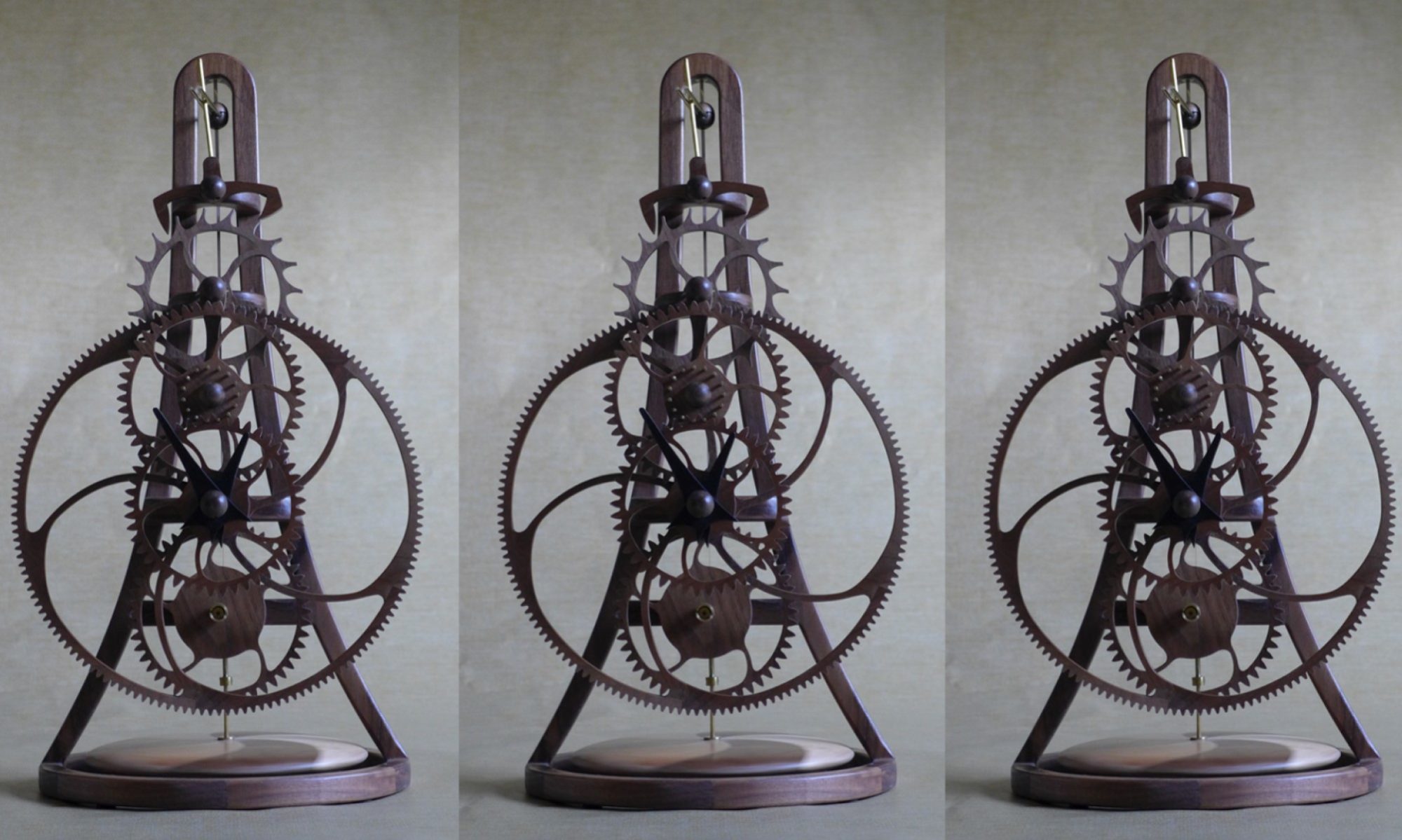
The rotation of the torsional pendulum is the primary kinetic element of the clock and on most of my clocks I use two contrasting woods to accentuate the visual impact of this motions. The design for this clock is a 4.5” diameter spherical torsional make from walnut and hard maple.

The pendulum is partially hollow with cut-outs to accommodate the weights. My plan is to cut the pendulum on the Zenbot CNC router. Because of the router cut depth limit, the pendulum will be constructed from 6 layers of ¾” thick wood. Each layer will be cut and then glued together. To get access to the weights, the pendulum is split horizontally with dowels to locate the upper and lower halves. Each layer is defined in my CAD software, TurboCAD, and the CUT3D software from Ventric is used to create the g-code toolpath. Because I rarely use this software it is always a learning experience and I spent most of today struggling to work out why it was not doing what I expected. I eventually worked it out and have generated the cutter path g-code files.

While working on the torsional pendulum I was testing the clock and tweaking the teeth when it stopped. The clock is now running well and I am keeping my fingers crossed that I have corrected all the “problem teeth”. However, experience on previous clocks is that lacquering the wheels will result in them distorting very slightly requiring additional tweaking.
I have several domestic tasks to do tomorrow, so I am not sure if I will get to cutting the torsional pendulum.