The clock ran for over 5 hours last night. Rather than chasing the last few “problem teeth”, I decided to concentrate on making the clock hands and the clock speed adjustment mechanism today.
The clock speed is regulated by the moment of inertia of the torsional pendulum and the torsional stiffness of the torsional pendulum spring. The inertia of the torsional pendulum is controlled by the number of weights in the pendulum and the distance of these of the weights from center of the pendulum. The torsion stiffness of the spring is set by the width, thickness and length of the spring. During the design and construction of the clocks the number of torsional pendulum weights and their radial location is set so that the clock keeps good time. I have developed a screw adjustment mechanism that changes the effective length of the torsional pendulum so that the clock owner can fine tune the clock speed. Below are a series of photos on the construction of the clock speed adjustment mechanism.


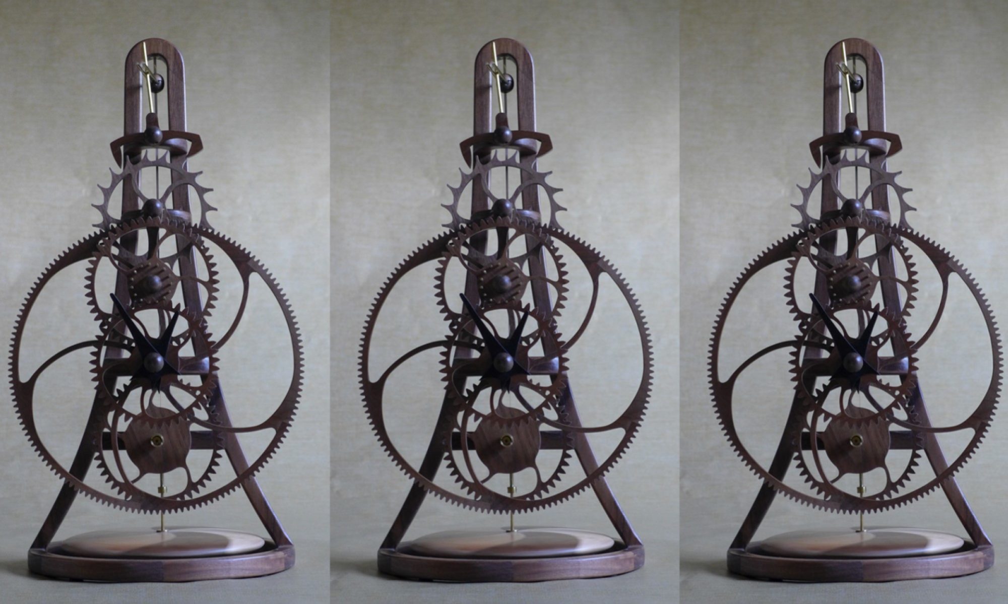
I leave the construction of the clock hands until I have nearly completed the clock so I can decide what shape to make the hand to compliment the clock design. My plan was to use a different wood for the hands so that they stand out from the clock, but with my local wood suppliers closed I will make the hands from walnut and dye them black. One cannot cut sharp internal corners using a router so I print the hand design on paper which I glue to the wood and then cut out with a scroll saw.


Because the pointer (finger) end of the hand is heavier that the other end, the hand is balanced by adding a brass disc to the other end (there must be a correct term for this) of the hand.


When I assembled the clock with the speed adjustment mechanism, I had a nasty discovery. As the torsional pendulum rotated it hit the clock frame ☹. To remedy this, I shortened the torsional spring by about an inch which caused the clock to run fast. To get the clock to keep time, I had to add more weights to the torsional pendulum. Unfortunately, the number of weights that are now required will not fit in the current design of the torsional pendulum and I will need to re-design it. My current thinking is to increase the diameter of the torsional pendulum by about ½” inch so that the number of weights can be reduced as they can be moved to a greater distance from the center of the pendulum. Tomorrow’s task is to think through the options and re-design the torsional pendulum.
For readers who have just joined the blog, an archive of prior posts (in reverse chronological order) is available at https://cedarclocks.com/category/creating-a-wooden-clock-electra-2/ .