The Clock is Complete!!!

The clock was still running this morning and I spent today replacing the brass bearing tube that was too short, trimmed the arbors and the pallet fork to their final lengths and permanently glued components that were press fit together.

I made the video below as I re-assembled the clock.

Video of the Assembly of the Clock

The clock is running well and the only things left to do are to make the final adjustment to the torsional spring length so that the clock keeps good time and run the clock for a few weeks to make sure that it is reliably.

Once I am happy that the clock is keeping good time and running well, I will offer the clock for sale.   To be consistent with the “pandemic pricing” of my other clocks (see the Purchase page), I am asking $2500 for this clock.  Please contact me at richard@cedarclocks.com if you are interested in purchasing the clock.

It has been almost exactly a month since I started daily posts on the construction of the clock.   Building the clock and writing these blogs has kept me busy in these strange times.  I hope you have found them interesting.  This is my last daily blog but I will write additional posts if there are any interesting updates and I plan to share detailed photos and a video next week.

Richard Cedar.
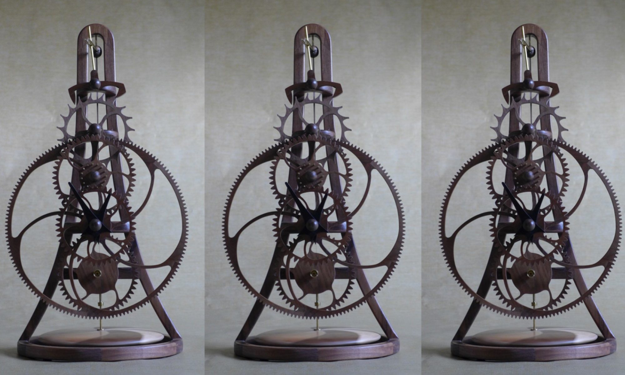
Clock Re-Assembled and Running

Started today by permanently gluing the 67 pinion rods in place and mounting the wheels on the arbors.  Initially, the clock ran intermittently.  Inspection revealed that more lacquer than expected had seeped under the masking tape on some of the great wheel teeth, so I lightly sanded them, re-assembled the clock again and it ran much better. 

Finished & Re-Assembled Clock Running 😊

I did not get to the hardware store to buy the bass tube that I need until late today, so I used the tube I had and will replace it tomorrow.

As I write this, the clock has been running well for over 4 hours and I am hopeful it will still be running tomorrow morning.

The plan for tomorrow is to replace the brass tube bearing that is too short, permanently glue the arbors to the frame and trim the pallet forks to their final lengths.   After that, the only things left to do is check that the clock runs consistently and adjust the length of the torsional spring until it keeps good time.

Beginning to Re-Assemble the Clock

A cold rainy southern Ohio day so I spent time applying a number of very light coats of lacquer to the clock hands until I was happy with the finish – They look good – and sanded and re-lacquered a few other parts that I was not totally happy with.   Enough lacquering, the clock is ready to re-assemble.

Started by assembling the remontoire winding arm that includes the winding motor, electric circuit board and the battery.  See earlier post for details.  

Assembled Remontoire Arm and Winding Wheel showing Battery Compartment
Remontoire Arm with Battery Compartment Closed
The back of the Remontoire Arm is fastened with wood screws so it can be opened should one need access to the electric motor or circuit board

Also attached the arbors (shafts) and mounting hardware to the clock frame so I am ready to assemble the wheel trains.   However, I need to purchase some brass tube as one of the bearing tubes is about 1/8” too short.  This was not an issue while I was testing the clock but not for the final product.  I will have to visit the hardware store tomorrow.

Re-Sand and Re-Lacquer

Finishing the clock is the slow part of clock construction.  I reviewed the surface finish quality on all the parts, sanded areas that I was not happy with, applied another coat of lacquer where needed and left them to dry.   There was nothing else to do other than wait for the parts to dry which was OK as it was warm and sunny and it was a pleasure to be outside.

By the end of the day all the parts were looking good other than the clock hands which need more work to get the surface quality I want.

Rain forecast again tomorrow, but there is little more I can do other than sand and re-lacquer the clock hands and any other areas that I decide need some more work.

A Gray Rainy Stay at Home Day – Ideal for Sanding

The weather forecast was correct – Today was gray and rainy in southern Ohio, ideal to lightly sand the lacquered wood parts and the application of a second coat of lacquer.  

Parts Laying on Newspaper to Dry after Lacquering – A very basic set-up
Wheels Hanging to Dry on Wire Rods through the Arbor Holes

Lacquer brings out the beauty of the wood grain but it also highlights any imperfection in the surface finish.  To stop the parts moving as they are being cut out by the CNC router, I add tabs to hold the part to the surrounding wood.  These tabs are then cut and the sanded smooth.   However smooth I think that I have sanded these tabs, the application of lacquer highlights where they were and I have to re-sand the surface.   Excess glue from joints that was not cleaned off also shows up after lacquering, especially on end grain wood. 

Although the second coat of lacquer is still drying, I am pleased with the surface quality on most of the parts.  A few parts will need a third coat and, even though I try hard to apply a thin coat of lacquer, a few runs have appeared that I will let dry, sand smooth, and re-lacquer the local area.

The plan for tomorrow is to re-sand the parts that need it and apply another coat of lacquer.

Rest Day

After weeks of gray skies and rain in Cincinnati, Ohio, we have beautiful spring weather today, so working outside in the yard was far more attractive than sanding clock parts in the workshop. I declared today a rest day from the clock.   The weather forecast for tomorrow is rain so I plan to resume working on the clock.

Finishing

It is difficult to write anything very interesting about lacquering the clock parts.   I use Watco Semi-Gloss aerosol lacquer that I spray on most of the parts laid out on paper.   The wheels are held on a “shaft” so that I can rotate / spin them one at a time as I spray them trying to get an even covering on the rims, spokes and hubs.    The spraying process is very inefficient, most of the lacquer misses the part, so I will go through several spray cans before I am happy with the finish.  However, I have found that I get a better finish by spraying multiple thin layers than trying to apply lacquer using a brush.

Watco Semi-Gloss Lacquer used to finish the clock parts
Wheels on a metal shaft so that I can spin them as I spray lacquer

Today, I sprayed one side of each part, waited for them to dry, turned them over and sprayed the other side.  I will leave the parts to dry over night and tomorrow I will sand as many of the surfaces as I can with 400 grit sandpaper, clean them with tack clock and then apply a second coat of lacquer.  My experience is that this will result in a good finish on some of the parts, but depending on the wood grain size and orientation, some parts will require a third, fourth, or even a fifth coat.  About as interesting as watching lacquer dry. 😊

Sanding, Cleaning and Masking

Sanded the final parts and then it was time to clean up the workshop that took most of the day.

Wooden clock parts sanded and ready for lacquering

My experience, and that of other wooden clock makers, is that wooden clocks run much better if the wheel teeth are kept as bare wood, not varnished or lacquered.   As I plan to finish all the wood parts using aerosol sprayed lacquer, I mask off all the teeth surfaces with long strips of masking tape prior to spraying.

Masking wheel teeth with long strips of masking tape
Masked wheel reading for lacquering

Tomorrow it’s time to apply the first coat of lacquer.

Sanding, More Sanding & Even More Sanding

As the clock is running well, and keeping good time, it was difficult to take it apart to start the finishing process.   Everything that was not permanently glued together has been disassembled and the wooden parts laid out for sanding.   I started with the frame that still needed considerable work blending the cross pieces in to the uprights.   I followed with the wheels and other parts using a sanding block where possible and folded pieces of sandpaper for the curved surfaces.   All surfaces are finally sanded using 400 grit paper.

I like to slightly round all edges (“breaking the edges”) by running a piece of sandpaper along them so that they are no longer sharp.  I learned from my days as a potter that even slightly rounding edges gives the piece a dramatically softer appearance.  

My plan is to have everything sanded before I start to apply lacquer to minimize the amount of dust in the air that can land on the surface while the lacquer is drying.  

As mentioned in an earlier post, the clock hands will be dyed black so that they stand out from the rest of the clock.   Because it takes time for the dye to dry, and it normally takes three or four dye applications followed by sanding, I dyed the hands today using TransTint black dye diluted with water.

Hands hanging to dry following dying

The plan was to sand all the part today but it did not happen and I have a few parts left to sand tomorrow.   I try to clean the worst of the mess from my workshop at the end of each day, however sanding leaves every surface covered in dust that I will clean up when I finish sanding tomorrow.  A necessary but not fun task.

Manufacturing the Final Parts of the Clock

Accomplished another milestone today with the manufacturing of the final parts of the clock, the hemi-spherical walnut caps that cover the brass collars on the end of the arbors and the collar on the torsional pendulum fork.   These caps serve no functional purpose, purely decorative, but I think they give the clock a “tidier” appearance.   The hemi-spherical caps are formed from walnut dowel rod, using a conventional router to round the end.  For the ¾” diameter caps, I use a 3/8” radius cutter with the router set-up so that as the dowel is rotated the cutter forms the hemi-spherical end to the dowel.

Using router to cut the hemi-spherical end on the walnut dowel

The end of the dowel rod is then cut off and I use the lather to drill the cavity in the dowel for the collar and cut off the hemi-spherical end cap.

Drilling the cavity in the cap using a drill collar to set the depth
Cutting off the hemi-spherical end cap

Finally, a hole is drilled in the side of the cap to access the collar clamping screw.

Drilling access hole for the collar clamping screw
Some of the walnut caps manufactured today
Clock with the walnut caps installed

Next step is to disassemble the clock and sand all the parts in preparation for finishing the clock with lacquer.  

Torsional Pendulum Installed on the Clock

The properties that make walnut ideal for wooden clocks, fine grained and hard, make it hard work and time consuming to sand, but once it is smooth the surface finish is beautiful   Today, I sanded the other half of the torsional pendulum, mated the two halves, sanded the joint and installed it on the clock.

Upper and Lower Halves of the Torsional Pendulum
Complete Pendulum
Video of the Clock Running with the Torsional Pendulum

Although constructing the torsional pendulum is very time consuming, in my opinion, it really changes and improves the dynamic impact of the clock.

There are only a few components still to made, the hemispherical end caps that I use to cover all the brass collars.  I plan to construct these small fiddly parts tomorrow.

First Half of the Torsional Pendulum Sanded – Looking Good

Sanding, checking the assembly, gluing and more sanding was the order of the day as I worked on the torsional pendulum.   I started by sanding by hand but soon realized that I needed a better solution so I designed and constructed a fixture to hold half the torsional pendulum in the lathe and use the lathe to sand it.  

Fixture holding half the torsional pendulum for sanding

I started with 60 grit and proceeded through 120, 220 and 400 grit to smooth the surface of the first half.

Torsional pendulum after sanding with 400 grit sandpaper
External surface of the torsional pendulum
Internal surface of the torsional pendulum

There are still a few surface imperfections that I will sand out.   I plan to do this tomorrow after I have sanded the other half of the torsional pendulum and can mate both halves of the pendulum and sanded the joint.

A Milestone – The Clock has Run Continuously for over 24 Hours

Past a major milestone today – The clock has run continuously for over 24 hours and is still running with a strong “tick”.  My experience is that once a clock runs for a day all the “problem teeth” have been corrected and it will continue to run indefinitely.

Video of the clock running with the temporary torsional pendulum

Today, I cut the other side (the walnut side) of the torsional pendulum on the CNC router. Next step is to glue the parts together and sand the surface smooth.

Torsional Pendulum Parts ready to assemble

As the surface finish is not as good as I would like, I am thinking about making a fixture to hold the torsional pendulum halves in my lathe to speed up sanding.

Tomorrow, I plan to start assemble the torsional pendulum and perhaps make the final parts needed for the clock, the arbor end caps.

Torsional Pendulum Cutting & Clock Beat

The domestic tasks did not take too long and I managed to cut one side (the maple side) of the torsional pendulum on the CNC router.   I’m concerned that my ¼” ball end cutter is not as sharp as it should be as the surface finish was not very good, but nothing a few hours of sanding will not correct.

Zenbot CNC router cutting the maple side of the torsional pendulum

The clock continues to run well.

As there is not much news today, I thought you might be interested in more technical details on the clock.   Below is a summary of the teeth on each wheel and pinion.   This tooth count result in a beat (the time between ticks) of 6.3 seconds or 570 beats per hour.

Number of teeth on each wheel and pinion

The plan for tomorrow is to cut the other side (the walnut side) of the torsional pendulum.

Torsional Pendulum Redesign

Recall that yesterday I found an issue with the clock design that resulted in the clock running too fast.  To remedy this, I need to increase the moment of inertia of the torsional pendulum but there is not enough room in the current pendulum design to increase the number of weights.   My original thinking was to increase the diameter of the pendulum allowing the weights to be moved radially outward.   I gave this some more thought this morning and realized increasing the pendulum diameter would have several undesirable consequences.    While pondering what to do, it occurred to me that if I re-orientate the weights the radius of their center of gravity would move outward increasing the pendulum’s moment of inertia.  I tested this on the temporary pendulum and it worked beautifully, the clock is keeping good time and I could reduce the number of weights so that they fit in to the original pendulum.

Original Torsional Pendulum Weight Configuration
New Torsional Pendulum Weight Configuration

The rotation of the torsional pendulum is the primary kinetic element of the clock and on most of my clocks I use two contrasting woods to accentuate the visual impact of this motions.  The design for this clock is a 4.5” diameter spherical torsional make from walnut and hard maple.

Digital representation of the Torsional Pendulum showing the contrasting woods design

The pendulum is partially hollow with cut-outs to accommodate the weights.   My plan is to cut the pendulum on the Zenbot CNC router.   Because of the router cut depth limit, the pendulum will be constructed from 6 layers of ¾” thick wood.   Each layer will be cut and then glued together.  To get access to the weights, the pendulum is split horizontally with dowels to locate the upper and lower halves.   Each layer is defined in my CAD software, TurboCAD, and the CUT3D software from Ventric is used to create the g-code toolpath.   Because I rarely use this software it is always a learning experience and I spent most of today struggling to work out why it was not doing what I expected.   I eventually worked it out and have generated the cutter path g-code files.

CUT3D simulation of the machining of the 6 layers needed to construct half the torsional pendulum

While working on the torsional pendulum I was testing the clock and tweaking the teeth when it stopped.   The clock is now running well and I am keeping my fingers crossed that I have corrected all the “problem teeth”.  However, experience on previous clocks is that lacquering the wheels will result in them distorting very slightly requiring additional tweaking.

I have several domestic tasks to do tomorrow, so I am not sure if I will get to cutting the torsional pendulum.

Constructing the Hands and Speed Adjustment Mechanism

The clock ran for over 5 hours last night.  Rather than chasing the last few “problem teeth”, I decided to concentrate on making the clock hands and the clock speed adjustment mechanism today.

The clock speed is regulated by the moment of inertia of the torsional pendulum and the torsional stiffness of the torsional pendulum spring.   The inertia of the torsional pendulum is controlled by the number of weights in the pendulum and the distance of these of the weights from center of the pendulum.  The torsion stiffness of the spring is set by the width, thickness and length of the spring.   During the design and construction of the clocks the number of torsional pendulum weights and their radial location is set so that the clock keeps good time.   I have developed a screw adjustment mechanism that changes the effective length of the torsional pendulum so that the clock owner can fine tune the clock speed.   Below are a series of photos on the construction of the clock speed adjustment mechanism.

Creating a slot in the top of the Spring Length Adjustment Tube
Slot in the top of the Spring Length Adjustment Tube after Soldering and Clean-up
Components of the Clock Speed Adjustment Mechanism
Completed Clock Speed Adjustment Mechanism

I leave the construction of the clock hands until I have nearly completed the clock so I can decide what shape to make the hand to compliment the clock design.   My plan was to use a different wood for the hands so that they stand out from the clock, but with my local wood suppliers closed I will make the hands from walnut and dye them black.  One cannot cut sharp internal corners using a router so I print the hand design on paper which I glue to the wood and then cut out with a scroll saw.

Hand Design Glued to ¼” walnut sheet
Cutting the sharp internal corner of the hand on a scroll saw
Scroll saw cut hand

Because the pointer (finger) end of the hand is heavier that the other end, the hand is balanced by adding a brass disc to the other end (there must be a correct term for this) of the hand.

Using fishing weights to determine the weight required to balance the hand
Brass discs are cut on the lathe to give the weight required to balance the hands
Current Status of the Clock – Note that the hands will be dyed black so that they will stand out

When I assembled the clock with the speed adjustment mechanism, I had a nasty discovery.   As the torsional pendulum rotated it hit the clock frame ☹.   To remedy this, I shortened the torsional spring by about an inch which caused the clock to run fast.   To get the clock to keep time, I had to add more weights to the torsional pendulum.  Unfortunately, the number of weights that are now required will not fit in the current design of the torsional pendulum and I will need to re-design it.   My current thinking is to increase the diameter of the torsional pendulum by about ½” inch so that the number of weights can be reduced as they can be moved to a greater distance from the center of the pendulum.   Tomorrow’s task is to think through the options and re-design the torsional pendulum.

For readers who have just joined the blog, an archive of prior posts (in reverse chronological order) is available at https://cedarclocks.com/category/creating-a-wooden-clock-electra-2/ .